Features Of A Fired Heater
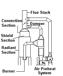
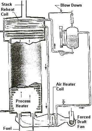
To look at various features of a Fired Heater, we can use a skecth of a generic, vertical tube fired heater with an air preheat system. The main features are detailed below.
Burner
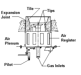
The burner in a vertical tube, cylindrical fired heater is located in the floor and fires upward.
Radiant Section
Cylindrical Radiant Section
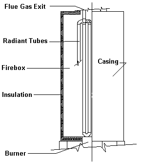
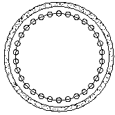
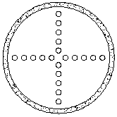
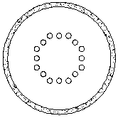
The radiant section in a vertical tube, cylindrical fired heater contains tubes in a vertical position. The tubes may be along the refractory wall, as in a circular pattern, or they may be exposed to the radiating flame from both sides, as in a cross or octagonal pattern.
Circular Tube Pattern:
Cross Tube Pattern:
Octagonal Tube Pattern:
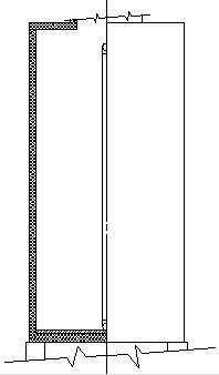
Vertical Tube Box Radiant Section:
Single And Multiple Cell Radiant Section
The radiant section in a vertical tube, box type fired heater contains tubes in a vertical position. The tubes may be along the refractory wall, or they may be located along the centerline of the box receiving radiant heat on both sides, or they may be located in both positions.
Single Sided Firing Only:

Double Sided Firing only:

Mixed Firing:

Other Tube Coil Designs
Hoop Coil Radiant Section:
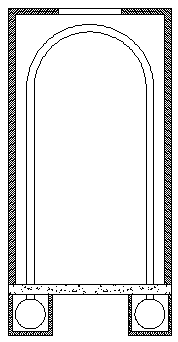
The radiant section has vertical tube coils in a hoop or hairpin design. The tubes may be as shown with the headers at the bottom, or they may be reversed with the headers at the top. The more common design is as shown with the burners down the centerline of the box, firing vertically. This design is used where the pressure drop must be very low since the path through each tube provides a design with many passes.
Shield Section (Bridgewall)
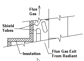
The shield section contains the tube rows that "shield" the convection rows from the direct radiant heat. Just below the shield tubes are two important monitoring points. The first is the "bridgewall" temperature which is the temperature of the flue gas after the radiant heat is removed including the radiant heat to the shield tubes above, but before the convective heat to the shield tubes. The other is the draft measurement at this point, since for most heater designs, if it is negative at this point, it is negative throughout the furnace.
Convection Section
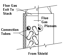
The convection section is located in the cooler flue gas stream. It often contains rows of extended surface tubes to improve the efficiency of the furnace. The flue gases can be cooled to a very low temperature, but caution must be used to avoid going below the dew point of the flue gas with the metal temperature of the tubes or surface, since this could cause corrosion.
Extended SurfacesModern convection sections frequently use extended surface to increase the overall heat transfer efficiency of the fired heater. The most common extended surfaces are of the following types.
Segmented Fins:These are usually one of the two types shown below.
High Frequency Continuously Welded
Standard Frequency Spot Welded
The standard frequency, spot welded, design is not used in fired heaters very often since this design is normally selected when using very thin, high density finning such as in a large heat recovery boiler. Most fired heater convections seldom use fins less than 0.049 inch thick. The standard frequency, spot welded fin also has a foot which presents a place where corrosion can occur if flue gases are corrosive or moisture is present.
Solid Fins:These are the most popular fins for modern fired heaters.
High Frequency Continuously Welded
These are used generally when the fuel is No. 6 or higher.
Resistance Welded
Thermal rating procedures for all these extended surface types are presented in section 4, Heat Transfer Concepts. Both segmented fin types are rated using the same formulas.
Flue Stack
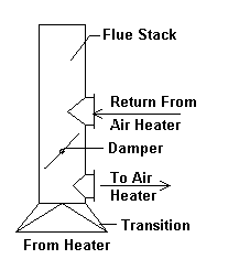
The flue stack on the heater is very important for several reasons. In addition to just getting the flue gasses up and out of the way where they won't endanger people, they also perform other functions. In the example shown, draft or flow of the flue gas is controled by an induced draft fan. In a natural draft furnace, the draft created in the stack is what "pulls' the flue gasses through the furnace convection.
Damper
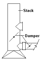
The main damper in the stack is used to control draft in the furnace. It is normal adjusted to achieve a negative 0.05 inches H2O pressure at the bridgewall. It is not used to control combustion air which is controlled by air plenum dampers or air registers at the burner(s). In the example used herein, it is used to redirect the flue gasses to the air preheat system.
Air Preheat System
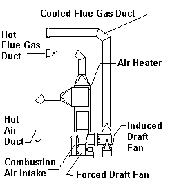
The air preheat system is used to preheat the combustion air going to the burners. Since it cools the flue gas further, while removing heat, it improves the efficiency of the furnace. Using an air preheat system will frequently result in overall efficiencies above 90%.
These systems utilize air heaters of various designs. Some designs of air heaters lend themselves to a smaller heater such as a tubular air heater mounted on the heater or a regenerative type heater which would more often be found on very large heaters. Some of these air heaters are discussed below.
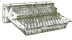
Regenerative Air HeaterThe regenerative air heater is widely used in the boiler and power generation industry. For this reason, when the fired heater industry developed a need for air heaters, these designs were the first to be used. They consist of a setting enclosing a large rotor which holds baskets of heat exchange surface. This rotor causes the baskets to pass through the hot flue gas, where the material heats up, and then through the cold air, which it heats. Even though these were very good at exchanging large amounts of heat, they had a downside of leakage from the higher pressure side(air) to the lower pressure side(flue gas) and of course they have moving parts. The sketches below show the basics of this type air heater.
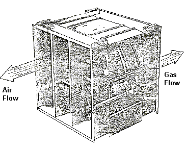 Baskets
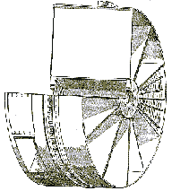 Rotor
Rotor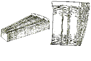 Recuperative, Tubular Air Heater
 Heating Medium Air Heater
This air heater comes Is part of a recirculating hot oil system which recovers heat from the flue gas exiting the fired heater and uses it to preheat the combustion air going to the burners.
Tubes, Pipe, & Fittings
Selecting the heater tube material and size to use in a heater design is really a matter of experience. As you work with different fired heaters for different services, you develop a knowledge of what fit before in a similar design, so you know where to start with a new design. But a few general rules can be used to start the selection.
For the typical, general purpose heater, using standard pipe sizes, the 4" pipe size will normally work out to be the most economical pipe size. The cost will generally go up with a smaller or larger pipe size. Likewise, a one or two pass heater will normally work out best. Using the flux rate, for the radiant section, that you desire for the furnace, and assuming 70% of the heat is absorbed in the radiant section, you can make some preliminary pressure loss estimates to get a preliminary tube size to start with.
In a similar manner, you can make some preliminary estimates to determine what the design metal temperature for the heater tubes need to be. With this temperature, you would select the least material that is good for the temperature. Eventual analysis may show that a higher alloy and a thinner wall may be more economical, so running calculations with several materials is always wise.
Typical generic, pipe, and tube specifications used for heater tubes:
| Generic Specification | Pipe Specification |
|---|---|
| Carbon Steel | A 234 WPB |
| 1¼ Cr ½ Mo | A 234 WP11 |
| 2¼ Cr 1 Mo | A 234 WP22 |
| 5 Cr ½ Mo | A 234 WP5 |
| 9 Cr 1 Mo | A 234 WP9 |
| 18 Cr 8 Ni | A 403 WP304 |
| 16 Cr 12 Ni 2 Mo | A 403 WP316 |
| 18 Cr 10 Ni Ti | A 403 WP321 |
| 18 Cr 10 Ni Ti | A 403 WP321H |
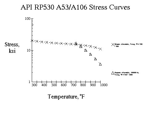
And other, more exotic materials for special furnaces are used as may be needed. The wall thickness required is normally calculated by using the API RP530 recommended practice, with the rupture allowable stress for 100,000 hours design life or the elastic allowable stress being used depending on the design tube wall temperature.
Tube Wall Thickness:For Elastic Design (lower temperatures)
And,
For Rupture Design (higher temperatures)
And,
Where,
| ts = Stress thickness, in |
| Pe = Elastic design pressure, psig |
| Pr = Rupture design pressure, psig |
| Do = Outside tube diameter, in |
| Se = Elastic allowable stress at design temperature, psi |
| Sr = Rupture allowable stress at design temperature, psi |
| tm = Minimum thickness including corrosion, in |
| CA = Corrosion allowance, in |
| F = Corrosion fraction as a function of B and n |
| Where, |
| B = CA/ts |
| n = rupture exponent at design temperature |
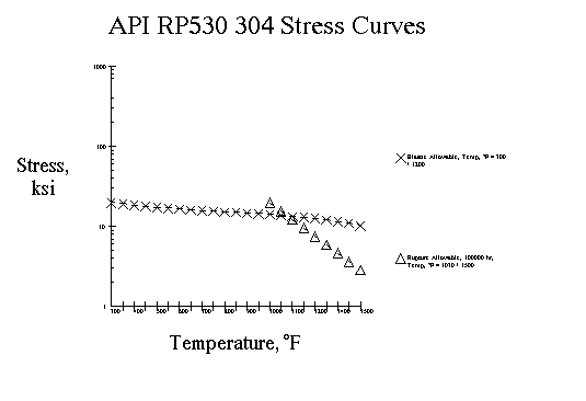
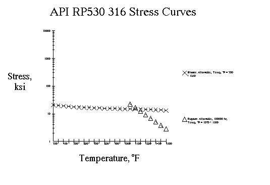
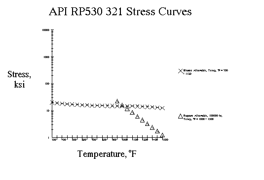
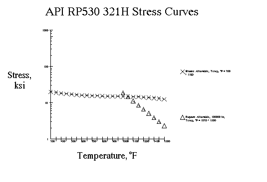
The tube metal temperature can be calculated as described in "Heat Transfer" section, under "Tube Wall Temperature Calculation" in this material. From this temperature, we can select the stress values from the following curves.
Editor's note: this data is out of date, but included for completeness as part of Hardie's original material. Use the FiredHeaterPro app to calculate API-530 thicknesses. FiredHeaterPro is always up to date.
Carbon Steel:
 ¼ Cr ½ Mo:
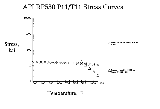 2¼ Cr 1 Mo:
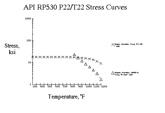 5 Cr ½ Mo:
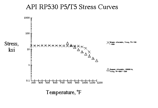 9 Cr 1 Mo:
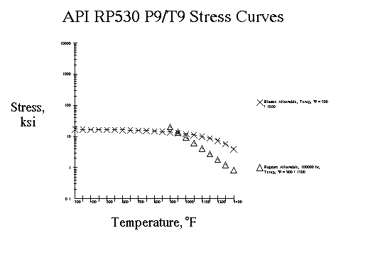 18 Cr 8 Ni:
 16 Cr 12 Ni 2 Mo:
 18 Cr 10 Ni Ti:
 18 Cr 10 Ni Ti:
Using the above stress values and formulas, we can now calculate the minimum wall thickness for a tube.
A little bit of confusion over why a pipe is called a tube, when it is in a heater, might be expected. But usage dictates that the heat transfer tubes be referred to as tubes, heater tubes, or furnace tubes, regardless of whether they are manufactured from materials specified as tubes or as pipes.
But, the usage confusion goes even deeper, since the spacing from the radiant tube center line to the inside of the refractory is generally 1.5 nominal tube diameters and the centerline to centerline of the tubes in normally 2 nominal tube diameters. Of course in this case, nominal tube diameters is really referring to nominal pipe diameters or "Iron Pipe Size"(IPS). Tubes don't have a "nominal" diameter, but rather they have an outside diameter(od) and an inside diameter(id). Of course, pipe also has an od and an id, but the legacy pipe descriptions of 2"(2.375"), 3"(3.5"), 4"(4.5"), etc., pipe sizes, still persist to this day. As well, the designation of pipe schedules such as 40, 60, 80, etc. are still in common use today. Therefore, many US programs still cater to this usage by including built in routines to convert these designations to od, id, and wall thickness which must be used in the formulas.
So even if you are designing a furnace in Europe, and you are using 6.625 inch od tubes, you would most likely still set the tube centerline to wall dimension to 1.5 IPS(or nominal diameters), or 1.5 * 6 = 9 inches. Likewise you would probably set the centerline to centerline tube spacing at two times the IPS(or nominal diameter), 2 * 6 = 12 inches. This also might be because the rolling equipment for the return bends exist for these "standard" 180° returns, or the tube support casting patterns may exist for this standoff. All of these constraints need to be considered when setting the dimensions of the furnace during the design.
When using tubes with the OD of a standard pipe size or using piping specifications, you would normally select a standard return bend to return the flow in a tube to the next tube. These returns bends are normally manufactured in two turning radii, called "short radius" and "long radius". The short radius return refers to a 180° return bend using a radius of one nominal diameter, ie, a 4" pipe size return has a radius of 4", and a 6" has a radius of 6", etc. The "long" radius bend has a radius equal to 1.5 nominal diameters so a 4" return has a radius of 6" and a 6" has a radius of 9". These standard returns are manufactured in most of the pipe schedules and are also available in "minimum wall" specifications.
Typical generic and pipe specifications used for return bends:| Generic Specification | Pipe Specification |
| Carbon Steel | A 234 WPB |
| 1¼ Cr ½ Mo | A 234 WP11 |
| 2¼ Cr 1 Mo | A 234 WP22 |
| 5 Cr ½ Mo | A 234 WP5 |
| 9 Cr 1 Mo | A 234 WP9 |
| 18 Cr 8 Ni | A 403 WP304 |
| 16 Cr 12 Ni 2 Mo | A 403 WP316 |
| 18 Cr 10 Ni Ti | A 403 WP321 |
| 18 Cr 10 Ni Ti | A 403 WP321H |
If using standard pipe fittings manufactured to standard pipe schedules, you would assume 80% of the standard wall thickness. If you are bending tubes or pipe for the application, you would need to calculate the thinning in the bend. The following calculator estimates the ratio of that thinning.
Tube Length Selection
Now that we have selected a tube diameter, material, wall thickness, and tube spacing, we need to decide what length the tubes should be. Pipe and tubes are manufactured in random lengths, ie, since the billet size varies, the actual length of the tube that is extruded, from a billet, varies from one tube to the next. For lower cost materials, it is usually cheaper to scrap pieces of tube, then it is to make center welds to try and use all the material. But another high cost factor involved with the length is the supports and guides for the tube in the furnace.
For vertical tubes, usually the overall furnace shape and size dictate the best tube length.As an example, for cylindrical radiant sections a length to diameter ratio of 3:1 might be the maximum desired, so the number of tubes and the length is balanced to achieve this ratio, while obtaining the surface required to meet the flux rate that is desired. The support and guide requirement varies depending on whether the tubes are supported from the top(hung) or bottom of the tubes.
In the horizontal tube furnace, the overall shape and size also figure into the equation. But, within these constraints, the span between supports must be considered. If the user has not specified a maximum span, then generally you would not want to exceed 35 tube OD's. This has been a general industry "not to exceed" rule of thumb used for many furnace designs. But care should be taken to consider the service and wall temperature of the tubes. Once you have determined the span between supports, the tube length would be selected to use the minimum number of supports, while avoiding unnecessary centerwelds, if centerwelds are allowed by user. All of this must be balanced with the fact that the pressure loss in the tubes is increased dramatically in the returns, so generally you want the longest straight tube possible. The pressure loss in the returns is reviewed in the "Process" section , under "Intube Pressure Drop".
Insulation & Heat Loss
The insulation in a furnace is extremely important for a number of reasons. The insulation provides a means of keeping the heat contained in the heater where it can be absorbed by the heater tubes, resulting in higher overall efficiencies. The insulation also keeps the external shell cooler making it safe for operating and maintenance personnel to safely work around the furnace. This cooler casing temperature also results in the structural stability of the overall structure.
Twenty years ago, most of the insulation used in fired heaters was the gunned or cast refractory. This material often, was mixed on site at the heater manufacturer's shop, and thus frequently varied in insulating properties. The more popularly used mixes like 1:2:4 LHV and others became standard and over time the insulating properties became very predictable. This was improved upon by the offering of proprietary mixes, by a number of companies, which were packaged in controlled environments and were thus more predictable in their application.
During the early eighties, ceramic fibers became accepted in the heater industry and since they are a much better insulator, they quickly caused a decline in the use of refractory. In general, 3 inches of ceramic fiber blanket could do a better job than 6 inches of refractory and weighed much less. As an example, if we have a hot face temperature of 1200 °F and an air temperature of 70 °F on a vertical wall with no wind blowing, 6" 1:2:4 LHV gunned has a cold face temperature of 205.5 °F where 3" 8# 2300°F ceramic fiber would have a cold face temperature of 161.2 °F. And this is with a weight less than 10% of the gunned refractory, which reduces freight cost. Furthermore, the ceramic fiber blanket does not require "drying" in the field as would be required with the refractory.
Refractory is still used in special furnaces and in areas where it is more durable or easier to install. The floor of a furnace which must be walked on during maintenance and inspection, may use castable refractory or brick, or both because it is more durable. End tube sheets, when they have multiple tube penetrations such as in an end supported tube convection may utilize gunned refractory because it is easier(less costly) to apply between the openings for the tubes then ceramic fiber blanket.
Heat Loss Through Insulation:The heat loss due to radiation may be calculated using the Stefan-Boltzman formula.
Where,
| hr = Heat loss by radiation, Btu/hr-ft2 |
| e = Emisivity of surface, assumed at 0.95 |
| T1 = Temperature of surface, °R |
| T2 = Temperature of surroundings,°R |
The heat loss due to free convection may be calculated using the following method.
Where,
| hc = Heat loss by convection, Btu/hr-ft2 |
| C = A constant, assumed at : |
| 1.79 for an arch or roof |
| 1.39 for a wall |
| 0.92 for a floor |
| Tavg = Average temperature of wall and surroundings,°R |
The heat loss due to forced convection, where the air velocity is greater than zero, may be calculated using the following method.
Where,
| hfc = Heat loss by forced convection, Btu/hr-ft2 |
| V = Velocity of air across surface, ft/sec |