Heat Transfer Concepts
Radiant Section Design
Applying basic radiation concepts to process-type heater design, Lobo & Evans developed a generally applicable rating method, that is followed with various modifications, by many heater designers. Reference Lobo & Evans, Heat Transfer in the Radiant Section of Petroleum Heaters, AICHE, Vol. 35, 1939. And a special thanks to R. N. Wimpress, who over the years, put all this in an understandable format.
This section of Fired Heater Design is divided into four main areas.
Direct Radiation In The Radiant SectionDirect radiation in the radiant section of a direct fired heater can be described by the equation shown
below.
Where,
| qr = Radiant heat transfer, Btu/hr |
| s = Stefan-Boltzman constant, 0.173E-8 Btu/ft2-hr-R4 |
| a = Relative effectiveness factor of the tube bank |
| Acp = Cold plane area of the tube bank, ft2 |
| F = Exchange factor |
| Tg = Effective gas temperature in firebox, °R |
| Tw = Average tube wall temperature, °R |
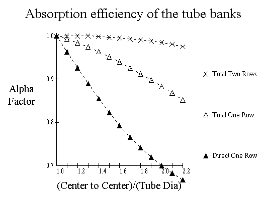
Relative Effectiveness Factor, a :
Because the tube bank does not absorb all the heat radiated to the cold plane, an absorption effectiveness factor, a, can be used to correct the cold plane area, depending on the arrangement of the tubes. The relative effectiveness factor can be described by the following curves:
For a single row in front of a refractory wall, use Total One Row. For two rows in front of a refractory wall, use Total Two Rows. For double sided firing, use Direct One Row.
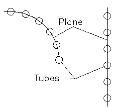
Cold Plane Area, Acp :
The normal heat-absorbing surfaces in a fired heater consist of a number of parallel tubes. In the case of a
fired heater design where the tubes are fired from one side only, the tubes are normally positioned in front
of a refractory wall. Part of the radiation from the hot gas strikes the tubes directly, while the rest
passes through and is radiated back into the chamber, where part is absorbed by the tubes. In the case of
tubes fired from both sides, as when the tubes are positioned in the center of the chamber, the tubes absorb
direct radiation from both sides. Expressing the tube area as an equivalent plane area simplifies this
calculation. The calculated cold plane area is the area of a plane through the tube center lines, whether
they are in a curved plane, such as in a cylindrical pattern or in a row side-by-side. For most tube panels,
the width would be equal to the center/center spacing of the tubes times the number of tubes. The length is
the length of tube exposed to the radiation. In the case of tubes penetrating a tube sheet it is the length
between tube sheets. But for tubes with the return bends inside the firebox, the length may be taken as the
distance from the centerline of the return on one end to the centerline of the return on the other end.
For a firebox with the tubes down the center, or other pattern which results in the tubes being fired from
both sides, the cold plane area would be twice the projected area.
 |
For single sided firing: Acp = Ntube*Stube*Ltube For double sided firing: Acp = Ntube*Stube*Ltube * 2 Where, Ntube = Number of tubes wide Stube = Tube spacing, ft Ltube = Effective tube length, ft |
Because the flue gas in the firebox is a poor radiator, the equation must be corrected using an exchange factor which is dependent on the emissivity of the gas and the ratio of refractory area to cold plane area. Since the radiant heat is reflected back into the firebox, by the refractory, a heater having a larger ratio of refractory surface relative to the tube surface, will absorb more heat. Since the tubes themselves are not perfect absorbers, the curves are based on a tube-surface absorptivity of 0.9. This is a value considered typical for oxidized metal surfaces. The overall radiant exchange factor, F, can be taken from the curve below as presented by Mekler & Fairall in Petroleum Refiner, June 1952.
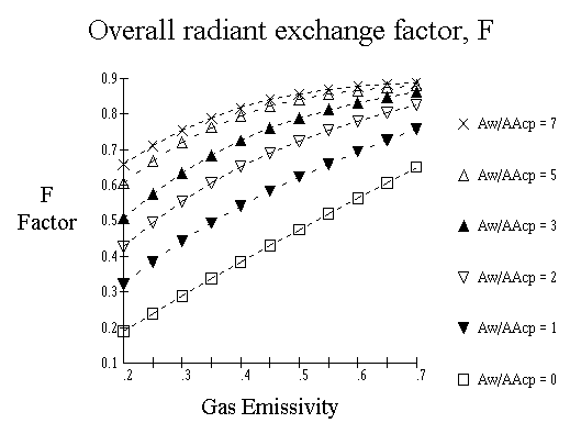
Aw/aAcp :
The equivalent cold plane area,aAcp, is the product of the effectiveness factor and the cold plane area as described above. The Aw can be described as follows,
| Aw = Ar - aAcp |
| and, |
| Aw = Effective refractory area, ft2 |
| Ar = Total refractory area, ft2 |
| aAcp = Equivalent cold plane area, ft2 |
The total refractory area, Ar, is simply the total of the refractory area exposed to the radiant section of the heater.
Flue Gas Emissivity :The gas emissivity can be described by the curve presented by Lobo and Evans, at AICHE, 32nd Annual Meeting, November 1939. The tube wall temperature has only a minor effect. Therefore, the emissivity can be correlated as a function of PL product and the gas temperature, Tg. Variations in tube wall temperatures between 600 and 1200°F cause less than 1% deviation from these curves.
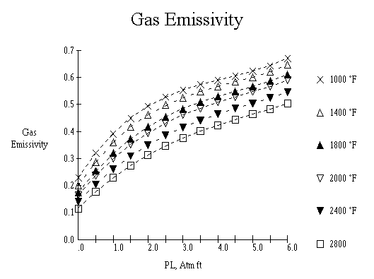
| PL = |
Product of the Partial Pressure of the carbon dioxide and water times the Beam Length, in atm-ft. |
Partial Pressure Of CO2 & H2O :
The only constituents normally in the flue gas that contribute significantly to the radiant emission are the carbon dioxide and the water, the sum of these are all that are considered. The Partial pressure of a gas component in atm's is the mole volume fraction percent of that component.
Mean Beam Length :
In computing the mean beam length, placement of the tubes must be taken into account. If the firebox is a rectangular shape with the tubes down the center, the beam length would be based on half the box. Beam lengths for other configurations, such as a cylindrical heater with an octagonal tube or cross tube layout, must be calculated with consideration for those cavities.
The mean beam length for heaters can be accounted for according to Wimpress in Hydrocarbon Processing, October 1963, as follows:
| For Box Type Heaters | |
| Dimension Ratio | Mean Beam Length |
| 1-1-1 to 1-1-3 1-2-1 to 1-2-4 |
2/3(Furnace Volume)1/3 |
| 1-1-4 to 1-1-inf | 1 x Smallest Dimension |
| 1-2-5 to 1-2-inf | 1.3 x Smallest Dimension |
| 1-3-3 to 1-inf-inf | 1.8 x Smallest Dimension |
| With the box dimensions, length, width, and | |
| For Vertical Cylindrical Heaters | |
| Length/Diameter < 2 | (((L/D)-1)*0.33 + 0.67)*D |
| Length/Diameter ≥ 2 | Diameter |
Effective gas temperature in firebox, Tg
For a radiant section that is considered "well mixed", this temperature is assumed to be equal to the temperature leaving the radiant section, i.e., the bridgewall temperature. For most applications, this is an acceptable assumption. But in a high temperature heater with a tall narrow firebox and wall firing, the Tg controlling radiant transfer may be 200 to 300 °F higher than the exit temperature. Tall, bottom fired cylindrical heaters are somewhere in between normal and this extreme. For those cases where this is true, either an adjustment such as using another temperature in this equation while using the exit temperature for the heat balance or dividing the radiant into zones for the balance calculations, should be considered.
Average tube wall temperature, TwTube wall temperature depends on the temperature of the process fluid and its transfer coefficient inside the
tube, the thermal resistance of the tube wall, the heat flux, and the fouling. The calculation of this
temperature will be treated in another section of this guide.
The average tube wall temperature as used herein, may be one of either the average temperature of the front
180° face of the tube, or the overall average for the full circumference. Some engineers follow one method
while the others go the other way. Either way, the overall difference between methods is relatively small.
Even though most of the heat exchanged in the radiant section is from radiant heat transfer, the convective heat transfer cannot be ignored. The heat exchanged by convection can be described with the following equation:
Where,
| qc = Convection heat transfer, Btu/hr |
| hc = Film heat transfer coefficient, Btu/hr-ft2- °R |
| At = Area of the tubes in bank, ft2 |
| Tg = Effective gas temperature in firebox, °R |
| Tw = Average tube wall temperature, °R |
Film heat transfer coefficient, hc
This value cannot be calculated precisely, and is usually selected by experience or rule of thumb. The arrangement of the tubes as well as the firebox design contributes to this factor. For horizontal tube, cabin type heater, which is normally small in size, this coefficient might = 1.5, where on large box heaters with multiple tube cells, it may be as high as 2.8. Vertical heaters with an L/D less than 2 would normally be designed with hc = 2, where for an L/D greater than 2.0, you could use 3.0.
The total heat absorbed by the radiant section tubes, now can be expressed by the following equation.
Where,
| qR = Total heat transferred to radiant tubes, Btu/hr |
| qr = Radiant heat transfer, Btu/hr |
| qc = Convective heat transfer, Btu/hr |
At this point, we are going to introduce another heat loss from the radiant section, radiant heat transfer to the shield tubes(if any), qS. This subject will be explored in detail later in the Heat Transfer Concepts. For the examples in this section, we will assume no shield tubes are present.
The procedures we have reviewed above gives us a method to either compute the heat absorbed, or we can
calculate the temperature we would need to transfer a specific amount of heat into our process coil. For us
to make a heat balance, we will need to determine the firing rate necessary to maintain that temperature.
This is accomplished by a heat balance around the fire box.
There are three primary sources of heat input to the radiant section, the burner release, qrls,
the sensible heat of the combustion air, qair, and the sensible heat of the fuel and any
atomizing medium, qother. Heat is taken out of the radiant section by the two heat transfer
methods previously explained, qR and qS, and by losses through the casing,
qloss, and sensible heat of the exiting flue gas, qout.
We can now set up the heat balance equation as follows:
| qrls = Heat released by burners, Btu/hr |
| qair = Heat in the combustion air, Btu/hr |
| qother = Heat in other items, Btu/hr |
| qR = Heat absorbed by radiant tubes, Btu/hr |
| qS = Radiant heat to shield tubes, Btu/hr |
| qloss = Heat loss through setting, Btu/hr |
| qout = Heat in gas leaving radiant section, Btu/hr |
qrls = Heat release by burners, Btu/hr
The burner release can be easily calculated for a gas when we know the composition of the fuel and the
heating values of the various components. For liquid fuels, the heating values are obtained by a calorimeter
test.
From these values and using the standard combustion equation, we can determine the composition of the flue
gas. As an example, the combustion of methane could be stated :
To try some calculations, click the button below to open another window to do some fuel combustion calculations:
qair = Heat in the combustion air, Btu/hr
The heat available in the combustion air, such as from preheated air, or using Gas Turbine Exhaust, etc., is taken as the heat content above 60 °F, since that is the design datum temperature for fired heaters. For the purpose of this discussion, radiant heat transfer, we are not going to take this into account, i.e., we will consider the air at 60 °F.
qother = Heat in other items, Btu/hrThe heat available in other items would include such things as the fuel when it is above 60 °F, atomizing air or steam, etc. These must be taken into account in heater design, however, for the purposes of these discussions, we are not going to include them.
qloss = Heat loss through setting, Btu/hrThese losses, referred to as Setting Loss or Radiation Loss are usually not calculated during heater rating calculations. They are normally accounted for by allowances, such as a percent of burner release or a percent of heat absorbed. Either way, the loss amounts to a rule of thumb. The actual losses may be calculated for the various surfaces and these methods are described elsewhere.
qout = Sensible heat in flue gas leaving radiant section, Btu/hr
From the flue gas composition, we can calculate the overall enthalpy of the flue gas, at a specific temperature, by adding the proportion each of the components contribute to the total. These enthalpies can be obtained from the following curves:
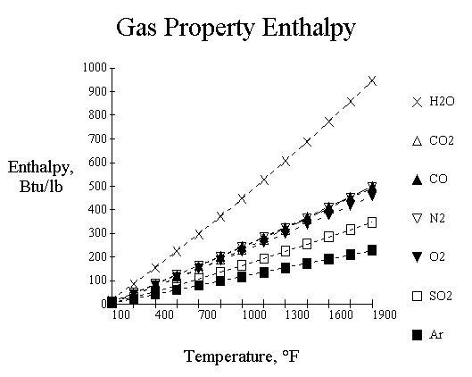
Since the flue gas composition remains consistent for a given fuel and excess air, the first thing we need to
do is perform the combustion calculation. This is what we did above to compute the burner release. The
enthalpy for a given temperature can now be calculated by obtaining the enthalpy for each component and
adding them together. And, as with the combustion calculation, this can be done by using a simple computer
program. To try this out, click the button below:
For this example, we will use the following data:
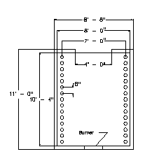
| Process Conditions: Heat Absorbed, Btu/hr = 9,500,000 Tube Wall Temperature, °F = 600 Fuel(Previous example fuel) = Gas Excess Air, % = 15 Mechanical Conditions: Tube Diameter, in = 4.500 Tube Spacing, in = 8 Tube Effective Length, ft = 26.000 Number Of Tubes = 30 Area Of Flue Gas Exit, ft2= 42 Radiant Arrangement = Box |
 |
For our a, Alpha, calculation,
(Center to Center)/(Tube Dia) = 8/4.5 = 1.7778
And from the graph, this gives a = 0.915.
However, since we are using a computer, we should introduce the ease of solving equations including reading graphs, by using a computer. The alpha value for total radiation to a single row of tubes can be expressed as:
a = 1 + 0.49 * Ratio / 6 - 0.09275 * Ratio ^ 2 + 0.065 * Ratio ^ 3 / 6 + 0.00025 * Ratio ^ 4
Even though, this equation simplifies the task somewhat, putting it in a JavaScript so the browser can do the work makes it even easier.
Acp = (No. Tubes)*Space*(Eff. Length) = 30*8/12*26.000 = 520.0
aAcp = 0.915 * 520.0 = 475.8
Ar = W*L*2 + W*H*2 + H*L*2-Exitarea*L = 8*26*2+8*10.333*2+10.333*26*2-42 = 1,076.644
Aw = Ar - aAcp = 1076.644 - 475.8 = 600.844
Aw/aAcp = 600.844 / 475.8 = 1.2628
To calculate the Exchange Factor, F, we need the flue gas emissivity, which we can get by interpolation from the curve presented above. As previously indicated, the Partial Pressure of the gas can be assumed to be the sum of the partial pressures of the CO2 + H2O. If we go back to the Fuel Gas Combustion calculation, we find that the mole percent of the CO2 = 0.085586 and the H2O = 0.172186, so the sum is 0.085586 + 0.172186 = 0.2578.
The beam length can then be obtained from the above table.
W : H : L = 8:10.3:26 = 1:1.3:3.3,
so,
Beam Length = 2/3(8*10.333*26)1/3 = 8.6012
and,
PL = 0.2578 * 8.6012 = 2.2174
however, in keeping with the other correlations, we should go ahead and setup a JavaScript to solve the Mean Beam Length, without manually interpolating the table.
The first thing we notice with this answer is that it doesn't match the hand calculated value. This is because the curve fit to facilitate all the table conditions and those in between, will not give the same value as we get when we select one formula or the next, with no transition. But, the calculated value is fine for our heat transfer calculations.
The emissivity curve requires that we know the Tg, which we don't know at this time. So for these calculations, we are going to initially assume this to be 1500° F. But, as above, we can now interpret the complicated emissivity curve with our browser.
Using our calculated emissivity, 0.427, and our calculated Aw/aAcp, 1.2628, we can now interpolate the curve for the exchange factor, F. Once again, we will use a JavaScript to do this.
So,
qr = 0.173E-8*475.8*0.597*((1500+460)^4 - (600+460)^4) = 6,631,794 Btu/hr
And,
qc = 1.5*918.918*(1500-600) = 1,240,539 Btu/hr
Therefore,
qR = qr+qc = 6,631,794 + 1,240,539 = 7,872,333 Btu/hr
Of course, this is far short of the 9,500,000 Btu/hr heat transfer that we needed to satisfy our process requirement. Experience would have caused us to recognize that we would have needed more surface to achieve a low exit temperature, i.e., bridgewall temperature of 1500 °F. This is a good time to introduce a new parameter, flux rate, into the discussion. The flux rate is a measurement of how hard heat is being pushed into the tubes. It is a criteria used by equipment users to tell a designer limits that he wishes to impose on the design.
| Fluxrad = Radiant tube flux rate, Btu/hr-ft2 |
| qR = Total radiant heat transfer, Btu/hr |
| Srad = Total radiant tube surface, ft2 |
For our example, the required flux rate is 10,339 Btu/hr-ft2, which is a fairly average flux rate, neither high, 18,000 Btu/hr-ft2, nor low, 6,000 /hr-ft2, for the range that direct fired heaters would generally fall in. A better guess for our exit temperature, would have been 1600 °F to 1650 °F. As you can see, the problem of doing this balance by hand is complicated. And, in the real world, it would be even more so, since the tube wall temperature, and tube process outlet temperature, inlet process pressure, etc., would have to be considered also.
So, lets open another window and do some calculations. Make some changes in the inputs and look closely at the results.
Now we need to review the overall heat balance equation again.
For these examples, the combustion air is at 60 °F, so the qair factor drops out of the equation.
The fuel is gas, so there is no atomization and we are assuming it to be at 60 °F, so the qother
factor also drops out of the left hand side. On the other side, we have no shield so the qS drops
out.
The equation can now be simplified to,
As mentioned above, the qloss is an allowance, and for this example, we can set it to be equal to 1.5% of the burner release, so,
Now we can restate, qrls in other terms,
| Wfuel = Fuel flow rate, lb/hr |
| Lhvfuel = Lower heating value of the fuel, Btu/lb |
And we can restate, qout in the following terms,
| RatioAirFuel = Air to fuel ratio, lb/lb |
| Enthfg = Enthalpy of flue gas, Btu/lb |
You will notice that all of these variables, we have a value for, except the amount of fuel, Wfuel. So it becomes a very simple matter to rearrange the equation and solve it for the amount of fuel required to maintain the Tg, that we determined we needed in the previous calculation.
Then, rearranging the equation, it becomes,
Substituting the values we developed earlier,
So the burner release and the flue gas flow,
And, what we really wanted to know, the efficiency of the heater,
This concludes the review of Radiant Section Design, but the following script will provide a window where all of the formulas can be tested for various designs.

Try it today and see how much time you can save!